
| Product Details | |
|---|---|
| Brand | JUTAI |
| Serial Number | JTAC-22 |
| Country of Origin | China |
| Certificate | CE/FCC |
| Payment & Shipping Terms | |
|---|---|
| Price Quote | Negotiate |
| Minimum Order | 1 pcs |
| Average Delivery Time | Sample order 3-4 days,normal order 5-10 days |
| Payment Method | TT/Western Union,PayPal |
| Package Details | 1 pcs per box |
| Ability to Supply | 10000Pcs/month |
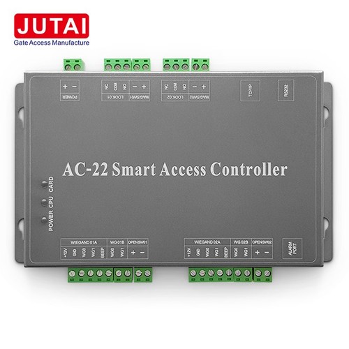
Two door access controller system is best for barrier gate , door access system, autogate and rfid reader application.this control panel can fulfill most demanding requirement in physical access control environment. Two door access control panel to manage one enrance and one exit. JUTAI support two door access control panel and gate access software and different type rfid reader. we can give you best whole solution and price.
Built in web server
Built-in web server where network configuration such as IP address, subnet mask, server IP can be easily done upon; No more factory programming needed as the firmware can be upgraded via the on-board web server.
Hign Performance
Based on the latest HCB (Hybrid Compact Board), JTAC-22 is a high reliability, high efficiency and highly integrated intelligent multi-application control panel targeted for physical access control industry. this control panel can fulfill most demanding requirement in physical access control environment.
Door interlocking
In doors interlocking within the control panel, no need external wiring. Cross-board interlocking is achievable by checking the interlocking signal coming from second control panel before granting the accessibility to the local control panel.
Super network processor and combined with mass storage technology
Adopting super network processor and combined with mass storage technology, and which can achieve real network data exchange.
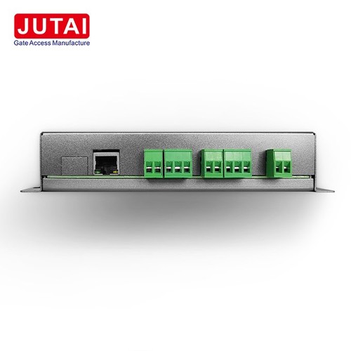
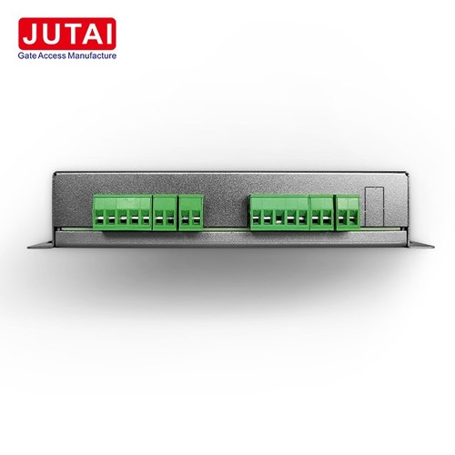
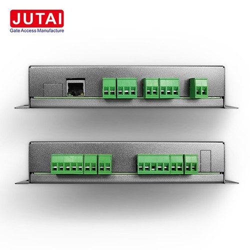
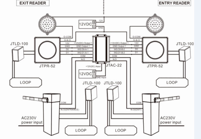
Door Access Controller Panel Technical Specification
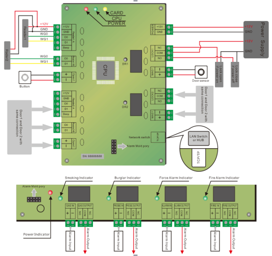
Door Control Pannel Connection Diagram
5-7M Semi-Active Hands Free Barrier Gate And Automatic Gate Access Control Solution
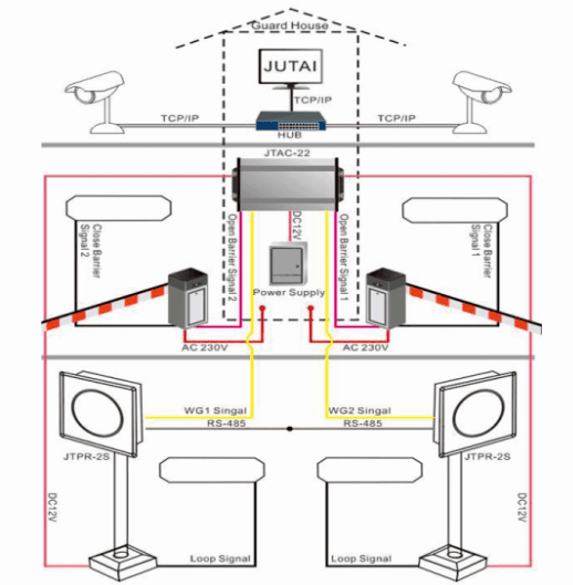
Connect To Software For One Entrance And One Exit With 5-7M Semi-Active Hands Free Barrier Gate And Automatic Gate Entrance And Exit Accee Control Solution
Normally FAQ
|
Common functions and solutions |
|||
|
Common malfunctions |
Access control / accessories |
Reason |
solutions |
|
Access control board don’t work when power supply |
Power light is not bright |
“+” and “-” supply wire reversed |
Connect line again |
|
|
Measure Voltage is low |
Power supply voltage is low |
Change 12VDC power supply |
|
For Rs485 Connection between CPU and controller don’t work |
Communication indicator RX light not bright |
Choose wrong COM port |
Choose correct COM port |
|
|
Communication indicator RX light not bright |
COM port is broken/or occupy |
Change other COM port |
|
|
Communication indicator RX light normally on |
Rs485 “A” and ”B”line reversed |
Correct line (A-A,B-B) |
|
|
Communication instructions RX light flashing |
The quantity of devices which connected with Rs485 is too much. |
Reduce controller quantity , or add signal-amplifier |
|
|
Communication indicator RX light flashing,not bright or normally on |
Rs485 communication interface broken or don’t match |
Using specified Rs485 |
|
|
Communication indicator RX light normally on or weak normally on |
Controller power not connect ground wire |
Connect ground wire |
|
|
|
Computer leakage or Power leakage |
Change leakage equipment and connect ground wire |
|
|
|
External high-voltage electrical interference |
Eliminate interference sources and connect ground wire |
|
For TCP/TP Connection between CPU and controller don’t work |
Rj45 port communication indicator light(orange) not bright |
cable port not properly, Communication wire is wrong |
Change communication wire and install |
|
|
|
A hub port wrong |
Change another hub port, or change new hub |
|
|
Rj45 port communication indicator light(orange) bright |
IP address have clash/ IP occupy by other equipment |
Setting Access Controller IP same with Computer IP |
|
|
|
Access Control IP different in one network segment |
Setting Access Controller IP same with Computer IP |
|
Read card can’t open door |
Access card indicator light , Read card is flashing |
Invalid card,Illegal card |
Please enroll the card |
|
|
|
Expire time or not in valid time |
Adjust card valid time |
|
|
|
Reader WG0 and WG1 wire reversed |
Connect reader and controller wire in correct |
|
|
|
Reader wire is longer |
Change short wire and new reader |
|
|
Access card indicator light , Read card is normally on |
Reader wire is wrong or reader broken |
Check wire.change new reader |
|
|
Access card indicator light normally on or weak normally on |
the interference of card reader circuit is serious |
Please replace the line and avoid interference sources (such as AC220 wires, motors, etc.) |
|
Press the button is invalid |
Access didn’t receive the signal of button |
Circuit malfunction |
Check the connection, connect the wire according to the right way. |
|
|
Access had received the signal of button |
The button had set the time interval |
Reset the valid time interval |
|
Door access electric plug locks, magnetic locks work abnormal |
Door access work normal, but the lock does not work. |
COM port of control board didn’t connect power + 12 |
COM port of control board connect power + 12, NO port connect positive pole of electric lock, electric lock negative pole connect power GND |
|
|
Door access work normal, but the lock work with opposite operation |
The NC port and NO port connected wrong |
COM port of control board connect power + 12, NO port connect positive pole of electric lock, electric lock negative pole connect power GND |
|
|
Door access work normal, but the lock powerless in work. |
The voltage is too low or the electric lock line is too long |
The work voltage should be in the scope in line with the requirement of the electric lock |
|
|
Electric lock unlock time is too short or too long. |
The adjusted lock delay time is not applicable. |
Adjust the lock delay time with the management software. |
|
|
Door access have alarm prompt, electric lock normally open all the time. |
Have fire alarm or smoke alarm.
|
Please check the source of alarm, eliminate the alarm. |
|
|
Door access is normal, but the electric lock normally open all the time.
|
Door access was set to normally open state.
|
Relieve the normally open state with the software, or long press the button for 5 seconds to close normally open or open normally open. |
|
Electric control lock go wrong |
High temperature or often burn electric control lock. |
The unlock time extended. |
Electric control lock unlock delay time set to 0.5 second. |
|
|
High temperature or often burn electric control lock. |
The line was connected wrong. |
COM port of control board connect power + 12, NO port connect positive pole of electric lock, electric lock negative pole connect power GND |
|
The expansion board of alarm is abnormal |
The light of expansion board is not bright.
|
The control board and alarm extension board connected wrong |
Please connect the control board and alarm extension board correctly |
|
|
Extension board can't alarm |
Circuit malfunction or alarm function is closed.
|
Check the input circuit and signal, check the alarm function whether effective. |
|
|
Often have alarm prompt easily
|
Circuit connected wrong or parameter settings wrong. |
Check alarm input line and check the alarm reason of controller property in the management system and barrier gate |
Fill out more information, We will get back to you within 24 hours.
5F,Mingjinhai Industrial Park, ShiyanTown, BaoAn,Shenzhen,China
jutaigateaccess2@gmail.com
Telephone : 86-0755-29573855
Business Phone : 8613143400257
Work Time :8:00-18:00(Beijing time)


